
 EN



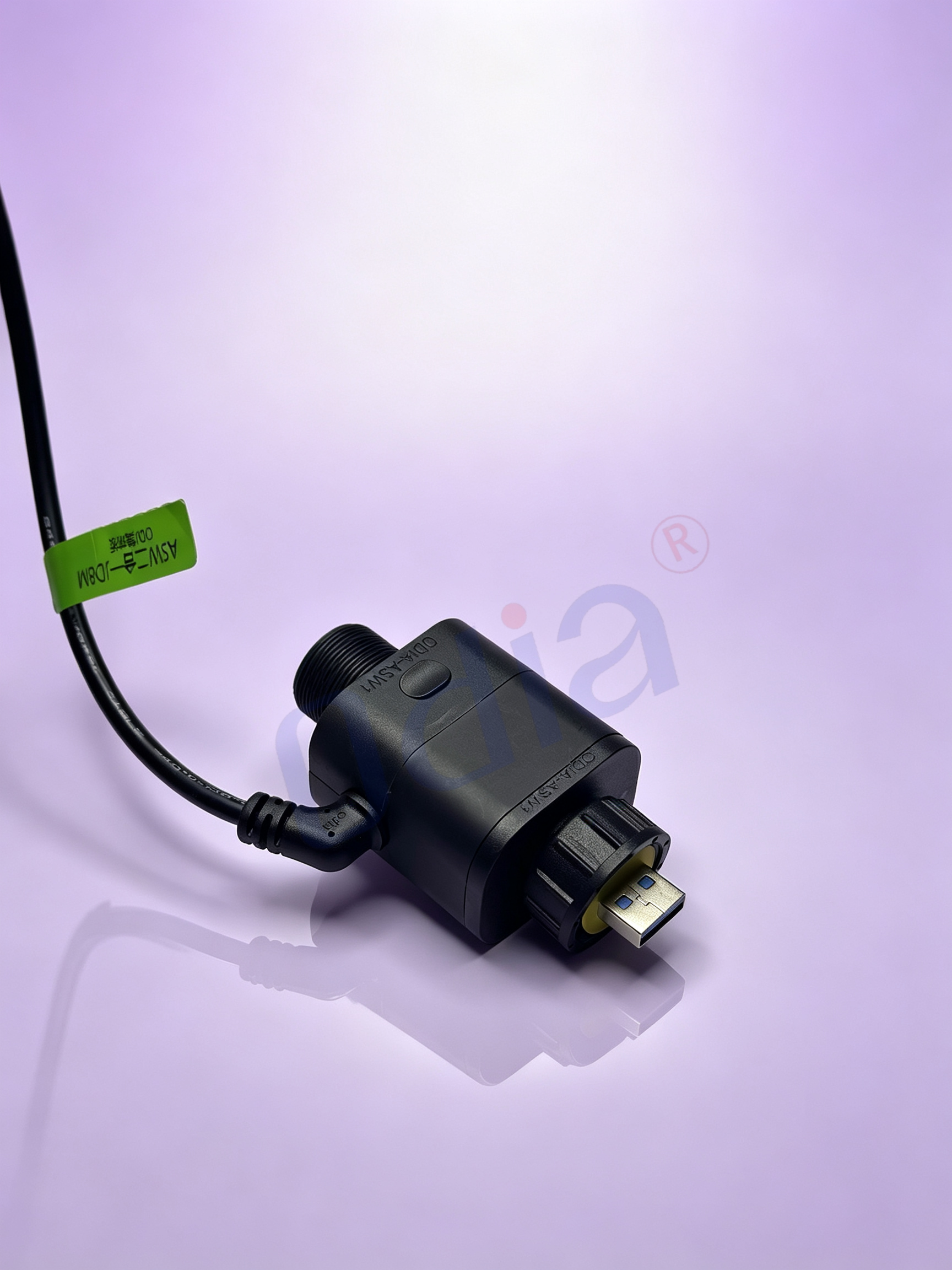
A connector listed at a certain current per contact is not telling the whole story. That number usually comes from a single energized contact sitting in still air at room temperature, terminated to a heavy-gauge wire. Drop the same contact into a sealed enclosure next to a dozen other loaded pins, and the thermal picture changes completely. Heat cannot escape the way it did on the bench. Adjacent contacts warm each other. The housing becomes a heat trap rather than a heat sink.
This is the first trap in harness connector selection: treating the catalog ampacity as a per-pin allowance and multiplying by pin count. The math feels intuitive and it is wrong. Current capacity is a thermal limit, not a property of the metal alone. The question is not how much one contact can carry in isolation, but how much the whole mated system can dissipate under the actual ambient and grouping conditions.
Derating Is a Thermal Calculation, Not a Courtesy Margin
IEC 60512-5-2 lays out the method for building a derating curve, and it is worth understanding what the curve represents. It plots permissible current against ambient temperature, with the upper end bounded by the limiting temperature of the contact and insulation materials. The curve bends downward as ambient rises because the allowable temperature rise shrinks. A contact that runs comfortably at a given current in a cool cabinet can exceed its material limits in a hot enclosure even if the current never changes.
Many qualification frameworks add another layer on top: a deliberate reduction factor of 0.8 applied across the current axis. That 20 percent margin absorbs crimp variation, contact aging, and manufacturing tolerance. It is not padding for its own sake. It is an acknowledgment that a fielded connector is not a laboratory sample. Bundle derating goes further still. A twelve-wire bundle can carry substantially less per wire than the same wires separated in free air, with derating factors in the range of roughly 0.53 to 0.63 depending on the standard and conditions. A connector selection that ignores bundle grouping is really a single-contact selection wearing a multi-pin housing.
| Selection variable | What the datasheet assumes | What the harness actually sees | Practical adjustment |
|---|---|---|---|
| Ambient temperature | 25 °C still air | Enclosed microclimate, often higher | Use local ambient, not room ambient |
| Contact loading | One energized contact | Multiple adjacent loaded contacts | Apply grouping or bundle factor |
| Wire gauge | Heavy gauge, short run | Production wire range, routed length | Confirm termination and heat sinking |
| Safety factor | None applied | Tolerance and aging exist | Apply 0.8 factor per IEC 60512-5-2 envelope |
Sealing Ratings Depend on the Accessory Package, Not Just the Housing
An IP67 or IP68 claim on a connector body is conditional. In many sealed connector systems, the high-pressure washdown rating, IP6K9K, only applies when a backshell is fitted. The housing alone may meet a lower threshold. This distinction matters in washdown corridors, food processing areas, and outdoor installations where spray is directed at the assembly from close range. Specifying the connector without the backshell and expecting the full rating is a common way to build a leak path into the design.
The wire seal is the other half of the sealing equation. Sealed connectors are designed around a specific insulation outside diameter range. A wire that is too thin for the seal cavity leaves a gap. A wire that is too thick distorts the seal and can prevent proper seating. The seal does not care about the conductor gauge. It cares about the jacket OD. That is why a complete sealing specification names the wire type, the OD range, and the cavity plug strategy for unused positions. An open cavity without a plug is a direct path to the contact chamber.
A retrofit in a chemical plant washdown zone illustrates the consequence. Assemblies that passed a bench continuity check began showing intermittent faults after exposure to cleaning cycles. The connector bodies were rated for splash protection, but the harness had been built with a jacket OD at the low end of the seal range, and several unused cavities had no plugs. Moisture tracked along the strands and collected at the contact interface. The fix was not a different connector family. It was a complete sealing package: correct backshell, matched wire OD, and cavity plugs on every unused position.
Mechanical Locking and Contact Plating Decide What Vibration Does Over Time
Vibration does two things to a connector. It works on the housing, trying to back out threaded couplings or unlatch a lever. It also works on the contact interface, where tiny relative motions can wear through plated surfaces. A locking mechanism addresses the first problem. Threaded couplings, wedgelock latches, and positive-lock levers all resist loosening. Connector Position Assurance features add a secondary check that the latch is fully engaged, which is useful when the mating action happens in a tight space and cannot be visually confirmed.
The second problem is plating. Tin-plated contacts are cost-effective and work well in stable, high-normal-force applications. Under vibration and thermal cycling, however, tin is vulnerable to fretting corrosion. Microscopic motion exposes fresh metal, which oxidizes, and contact resistance climbs. Gold plating resists this because the noble surface does not form a resistive oxide film. Mixing gold and tin in a mated pair is worse than either alone. The galvanic difference accelerates corrosion at the interface, and standards and manufacturer guidance both treat that pairing as an engineering violation rather than a compromise.
The practical rule is to match plating across the mating interface and to match the plating to the duty cycle. A connector that will be mated and unmated repeatedly benefits from a noble metal finish. A tin system can serve a fixed, protected joint if the normal force is adequate and the environment is controlled. The failure mode does not appear as a sudden open. It shows up as a slowly rising resistance that only becomes visible when the circuit is loaded.
Termination Method Is a Reliability Decision, Not a Line Speed Decision
Crimping and soldering both produce reliable joints when the tooling, materials, and process are right. The difference is where each method stores its risk. A properly made crimp is a gas-tight cold weld per IEC 60352-2. The compression forces the strand and contact materials to flow together, and no air reaches the interface. The joint stays flexible up to the contact, which is exactly what a vibrating or flexing harness needs.
A soldered joint introduces a rigid zone where solder wicks into the stranded conductor. Under bending or vibration, that transition acts as a stress riser. The strands can fracture at the boundary between the stiff soldered section and the flexible wire beyond it. For conductor-to-terminal connections in automotive and aerospace harnesses, Class 3 workmanship under IPC/WHMA-A-620 treats crimping as the required method and places strict limits on solder in those joints. The standard also requires full-cycle crimp tools for Class 3, which speaks to the real variable: process control. A hand tool of unknown calibration can make a joint that looks acceptable and performs like a weak link.
The honest limitation is that crimping only delivers its reliability advantage when the terminal, wire, and tool are a matched set, and when pull tests and crimp height checks confirm the setup. A bad crimp is not better than a good solder joint. The point is that a validated crimp process is easier to repeat across a production run than a hand-soldered joint, and its failure modes are easier to catch with routine inspection.
Standards Set the Acceptance Floor, and Process Holds the Assembly Above It
IPC/WHMA-A-620 provides the workmanship framework that both buyer and builder can audit against. It covers wire preparation, crimp terminations, connectorization, and inspection methods, with Class 3 representing the strictest acceptance envelope. Referencing the standard in a drawing package is necessary, but it does not by itself guarantee consistency. Two suppliers can both claim A-620 compliance and still differ in tool calibration discipline, pull-test frequency, and how they handle a wire that sits at the edge of the seal OD range.
A connector selection is only as good as the drawing that captures it. The drawing should name the connector family, the contact plating, the wire type and OD range, the sealing accessories, the workmanship class, and the inspection method. Vague notes invite interpretation, and interpretation is where variance enters the build.
Odia approaches harness connector selection around that practical gap: matching connector, contact, and wire specifications before release, holding crimp tooling within calibration, and tracing material lots so a field question can be answered with records rather than recollection. No process eliminates every failure mode, and a connector chosen against an unrealistic ambient assumption will still struggle. The aim is to make the difference between a good specification and a good build as small as it can be, batch after batch.
Table of Contents
- Derating Is a Thermal Calculation, Not a Courtesy Margin
- Sealing Ratings Depend on the Accessory Package, Not Just the Housing
- Mechanical Locking and Contact Plating Decide What Vibration Does Over Time
- Termination Method Is a Reliability Decision, Not a Line Speed Decision
- Standards Set the Acceptance Floor, and Process Holds the Assembly Above It

