
 EN



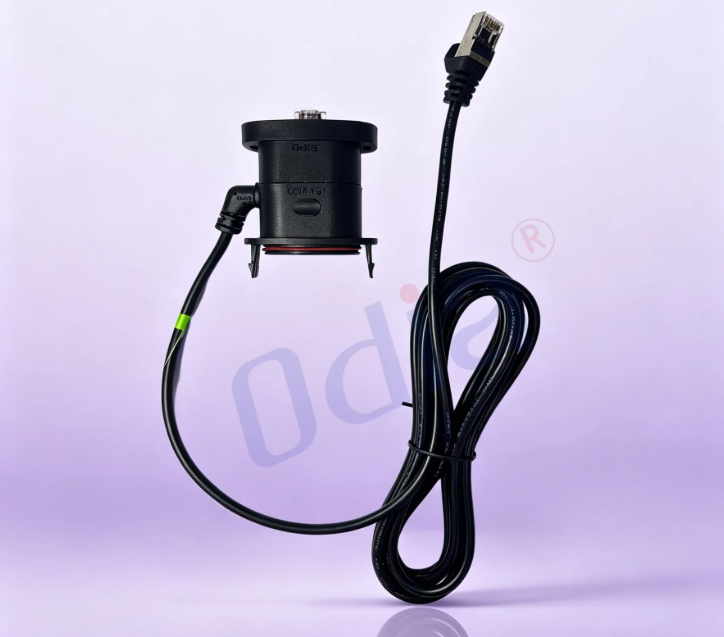
The Weak Point Is Almost Never the Cable Itself
Pull apart a failed cable assembly and the conductor is usually intact somewhere in the middle of the run. The damage sits at the exit of the connector, where a flexible jacket meets a rigid body. That transition is a fulcrum. Every bend, yank, and vibration cycle concentrates stress in a short section of copper stranding and insulation. A screw-on backshell and a piece of heat shrink can cover that zone, but covering is not the same as controlling it. Overmolding changes the mechanics at that junction rather than hiding it, and that is where most of the durability gain comes from.
The distinction matters because a lot of assemblies look protected. Heat shrink is cheap, fast, and visually tidy. It also leaves the cable free to bend at a sharper angle right where the termination lives. The failure mode does not announce itself at incoming inspection. It shows up after a few thousand cycles in the field, usually as an intermittent open that disappears when the harness is wiggled.
Chemical Bonding Turns Two Parts Into One Continuous Structure
The core reason overmolded assemblies outlast assembled ones comes down to adhesion at the interface. When the injected polymer is chemically compatible with the cable jacket, the heat of the melt causes the two materials to diffuse into each other at the molecular level. The result is not a sleeve sitting over a jacket with a mechanical grip. It is a continuous plastic transition from the connector body into the cable jacket, with no seam for contaminants to enter and no slip plane for force to exploit.
Data from adhesion-based overmolding shows how much this matters. In pull-out tests, PUR overmolding raised pull-out strength by roughly 25 percent over a reference cable, and PA overmolding raised it by about 51 percent. The failure mode is telling: the break occurred within the cable sheath itself rather than at the overmold-to-jacket interface, meaning the bond was stronger than the material around it. That is the opposite of a heat shrink joint, where the adhesive is the weak link and the tubing can slide or peel under sustained load.
A practical consequence follows: jacket and overmold chemistry must be matched. TPU overmold on a PUR or TPU jacket is a different animal from TPU over PVC. Without that compatibility, the assembly still has a molded shape, but the bond is superficial and the durability claim collapses.
Strain Relief Geometry Spreads Bending Moment Instead of Concentrating It
A molded strain relief is not just a blob of plastic around the connector. The geometry determines where bending energy lands. A solid tapered boot looks clean, but it can push the stress concentration right to the base of the connector, which is the worst possible location. A segmented or ribbed profile, by contrast, distributes the bending moment across its length in a cascading gradient, so the copper stranding stays inside its elastic range instead of work-hardening and cracking.
Finite element analysis of these profiles makes the difference concrete. A poorly designed solid strain relief shows a severe stress spike at the connector base, with flex life in the range of tens of thousands of cycles. A segmented profile built around the same cable and material can push the target into the million-cycle territory, provided the dynamic bend radius stays above roughly ten times the cable outer diameter. The ribbing is not cosmetic. It is a mechanical spring that controls the curvature the cable sees.
A chemical plant retrofit illustrates the field consequence. Assemblies in a washdown corridor had been finished with adhesive-lined heat shrink and were failing at the connector exit within a short service window. The conductors were fine. The jacket had stiffened under chemical exposure, and the heat shrink provided no graduated flexibility, so the bend radius at the termination dropped below the cable’s minimum. Switching to a ribbed TPU overmold bonded to a compatible jacket moved the failure point out of the connector exit zone entirely.
Sealing Is a Byproduct of Continuity, Not an Added Gasket
Moisture does not usually enter a cable assembly through the jacket wall. It wicks along the copper strands from an unsealed transition, driven by capillary action and thermal cycling. A mechanical backshell with an O-ring can seal the housing, but the gap between the overmold and the jacket remains a potential leak path if the bond is only mechanical. Overmolding removes that path because the melt fills the interstitial spaces and fuses with the jacket surface.
This is why overmolded assemblies are the default route to IP67 and IP68 ratings when the design is validated properly. The rating is not automatic. It depends on material pairing, tooling quality, and process control. But the mechanism is more robust than relying on a compressed gasket or a adhesive that can degrade. In high-pressure washdown conditions, adhesive-lined heat shrink is more susceptible to capillary leak paths over time, while a properly bonded overmold with a compatible jacket creates a homogeneous barrier with no seam to breach.
| Feature | Overmolded assembly | Screw-on backshell | Adhesive-lined heat shrink |
|---|---|---|---|
| Strain relief quality | Excellent, geometry tunable | Good, mechanical clamp | Fair, limited flex control |
| Sealing mechanism | Chemical bond, no seam | O-ring dependent | Adhesive dependent |
| Vibration resistance | Cannot loosen | Screws can back out | Can abrade or peel |
| Pull-out strength | Bonded interface, often exceeds jacket strength | Clamp-limited | Adhesive-limited |
| Upfront tooling | Mold required | None | None |
| Unit cost at volume | Low | High, manual assembly | Medium, manual labor |
The trade-off is honest: overmolding requires a mold and a validated material pairing. For prototypes and very low volumes, heat shrink or a boot can be the rational choice. The durability advantage only justifies the tooling when the assembly is going into motion, moisture, or vibration, and when the volume supports a proper mold.
Standards Draw a Line, but Process Consistency Decides Which Side of It the Assembly Lands On
IPC/WHMA-A-620 gives overmolding a defined acceptance envelope. For Class 1, an outer mold capturing 75 percent of the wire or jacket circumference is acceptable. For Class 2 and Class 3, the molded material must conform to the entire circumference contour of the jacket, and gaps or exposed insulation are defects. Those criteria are useful because they force a conversation about what “fully bonded” actually means in inspection terms. A Class 3 overmold is not just present. It is continuous around the jacket, with no voids or delamination at the interface.
The gap between a compliant sample and a compliant production lot is where sourcing decisions get made. Mold temperature, injection pressure, material dryness, and jacket surface condition all shift the bond quality. A process that produces a textbook first article can drift if those variables are not held. That is the unglamorous part of overmolded durability, and it is usually the part that determines whether the assembly is still sealed after a few years of thermal cycling.
Odia works on the mold-and-material side of this equation: matching overmold compound to jacket chemistry, holding injection parameters within a validated window, and checking bond integrity and dimensional conformance across production rather than only at first article. The durability of an overmolded cable assembly is not a single feature that can be added at the end. It is the sum of a compatible interface, a geometry that manages bending, and a process that repeats. Get those three aligned, and the connector exit stops being the weak point.
Table of Contents
- The Weak Point Is Almost Never the Cable Itself
- Chemical Bonding Turns Two Parts Into One Continuous Structure
- Strain Relief Geometry Spreads Bending Moment Instead of Concentrating It
- Sealing Is a Byproduct of Continuity, Not an Added Gasket
- Standards Draw a Line, but Process Consistency Decides Which Side of It the Assembly Lands On

