
 EN



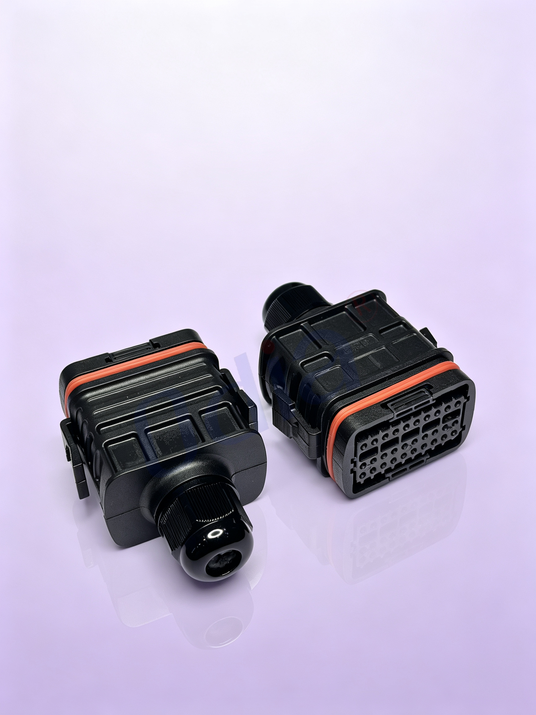
A cable assembly spec that begins with a connector part number is already behind. The environment writes the first draft. Temperature swing, chemical exposure, flex frequency, washdown cycles, and the presence of VFD-driven motors all narrow the real options before a single wire gauge is picked. In one plant retrofit, a batch of assemblies passed bench continuity checks but started failing within months because the jacket material had been chosen for indoor cabinet use and was routed through a washdown corridor. The conductors were fine. The jacket swelled, the shield bond degraded, and intermittent faults showed up only under vibration. Environmental mismatch rarely announces itself at incoming inspection. It surfaces later, usually at the worst possible time.
The practical move is to treat ambient conditions as a design input, not a checklist item. A cable assembly expected to live near a 105 °C exhaust manifold and one bolted to an indoor panel share almost nothing in insulation class or bend radius behavior. The same logic applies to exposure: cutting fluid, hydraulic mist, UV, and ozone each attack different polymer families at different rates. Specifying for the harshest sustained condition, rather than the average, tends to cost less than a mid-life replacement campaign.
Electrical Derating Is the Starting Point, Not an Afterthought
Current ratings on a datasheet assume a single conductor in free air at a reference ambient. A bundled assembly inside a cabinet or conduit is none of those things. Derating is where a lot of early failures get designed in, quietly. A connector contact rated for a certain current in isolation may need a bundle derating factor applied before the assembly carries real load. Military and aerospace practice has used altitude and bundle derating for decades for exactly this reason. The same discipline belongs in industrial and commercial assemblies, even when nobody asks for the calculation.
The derating curve is not a suggestion. It reflects heat that cannot escape. In a dense bundle, adjacent conductors heat each other, and the connector body becomes a thermal bottleneck. A conservative approach is to assume the connector, not the wire, sets the assembly ceiling, then verify with a temperature-rise test rather than trusting contact ampacity alone. IEC 60512-5-2 and similar methods exist for a reason: they force the specifier to look at the assembly as a thermal system, not a collection of parts.
Bend Radius and Flex Life Decide Field Reliability More Than Conductor Size
Bend radius is one of the few parameters where field data is unusually clear: cables pushed below recommended limits may still pass a continuity test, but their RF and mechanical margins shrink. Controlled tests on coaxial assemblies have shown that performance degrades gradually as bend diameter drops, with a recommended permanent bend radius well above the point of catastrophic failure. In dynamic flex applications, the failure mode is more deceptive. A NASA flex harness life test recorded rising trace resistance and open circuits at roughly ten percent of planned flex cycles, long before a simple go/no-go check would flag a problem. The harness worked cold. It just did not survive the mission profile.
The implication for specifying cable assemblies is direct. If the route involves repeated motion, a drag chain, or a tight enclosure, the flex requirement belongs in the drawing as a cycle count and a minimum dynamic radius, not a vague note to “route carefully.” Static bend radius and dynamic bend radius are different numbers, and treating them as interchangeable is a common way to lose field reliability without ever seeing an incoming inspection failure.
Shielding Is a System Property, and the Connector End Usually Sets the Limit
A braid with high optical coverage can still leak if the shield terminates poorly at the backshell. Transfer impedance is the better specification because it measures the shield circuit as a whole, including connectors and termination, rather than judging the cable jacket in isolation. Published limits for shielded connection systems tighten as frequency rises: a transfer impedance of -25 dB-Ω at 30 MHz and -10 dB-Ω at 500 MHz represents a typical envelope for a well-terminated assembly, with more negative values indicating better shielding. A cable that looks impressive on a braid coverage chart can miss those numbers if the pigtail is long or the backshell bond is resistive.
The engineering takeaway is to specify shielding effectiveness or transfer impedance at the system level and to require a test method that includes the mated connector interface. Real-world cable assemblies that achieve excellent attenuation, in the range of -70 dB-Ω, do so because the shield termination and connector interface are treated as part of the shield, not as an afterthought. If a spec only says “shielded,” it is not saying much.
Material Choice Is Where Compliance and Practical Durability Intersect
Insulation and jacket compounds get compared on temperature first, but the decision rarely stops there. Halogen content, smoke behavior, abrasion resistance, and flexibility over the service temperature range all matter, and they pull in different directions. PVC remains a workhorse for general-purpose indoor assemblies because it is inexpensive and flexible, with typical maximum conductor temperatures from 60 °C to 105 °C. PTFE reaches up to roughly 260 °C with excellent chemical resistance, but it is stiffer and costs several times more than PVC. LSZH compounds sit in the middle on temperature but exist specifically to reduce smoke and corrosive gas in enclosed spaces where evacuation is difficult.
| Material family | Typical max temperature | Flexibility | Halogen-free | Typical fit |
|---|---|---|---|---|
| PVC | 60–105 °C | Good | No | General indoor, cost-sensitive runs |
| PTFE | up to ~260 °C | Limited | No (fluoropolymer) | High heat, chemical exposure |
| TPU / TPE | ~90–125 °C | Excellent | Formulation-dependent | Flexing, abrasion, oil mist |
| LSZH compound | ~90–125 °C | Moderate to good | Yes | Enclosed spaces, transit, marine below decks |
A common mistake is to pick the highest-temperature material as a default. PTFE in a flexing application can be a liability if the bend radius is tight, and the cost premium buys nothing if the real threat is abrasion rather than heat. The honest answer is that no single compound wins across every column. The spec should state the dominant failure threat, then choose the material that handles that threat without creating a new weakness elsewhere.
Standards Set the Floor, Process Control Sets the Difference
IPC/WHMA-A-620 is the reference most cable assembly houses cite, and for good reason: it defines workmanship and acceptance criteria for terminations, shielding, overmolding, and marking in a way that both buyer and builder can audit against. The current revision, Revision F, was published in October 2025, superseding the prior edition. Referencing a workmanship standard is necessary but not sufficient. Two suppliers can both claim A-620 compliance and still differ in crimp tool calibration discipline, pull-test sampling, and how they handle engineering changes on the floor.
The gap between “certified to a standard” and “consistent in production” is where sourcing decisions actually get made. A drawing package that specifies the standard, the class, and the inspection method gives the builder a clear target. A package that says “build to IPC” without class or test scope invites interpretation, and interpretation is where variance enters.
Odia approaches cable assembly around this exact gap: the manufacturing side is organized around drawing-level tolerances, in-process pull and continuity checks, and material traceability that holds up when a field question arises. The point is not to claim that process control eliminates every failure mode. It does not. The point is to make the difference between a good drawing and a good build as small as possible, batch after batch. That is the part of specifying cable assemblies that does not show up on a datasheet, and it is usually the part that determines whether the assembly is still in service three years after installation.
Table of Contents
- Electrical Derating Is the Starting Point, Not an Afterthought
- Bend Radius and Flex Life Decide Field Reliability More Than Conductor Size
- Shielding Is a System Property, and the Connector End Usually Sets the Limit
- Material Choice Is Where Compliance and Practical Durability Intersect
- Standards Set the Floor, Process Control Sets the Difference

