
 EN




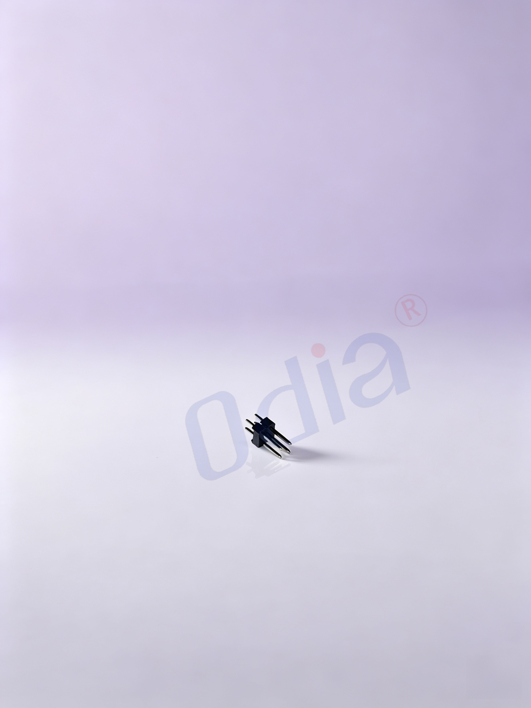
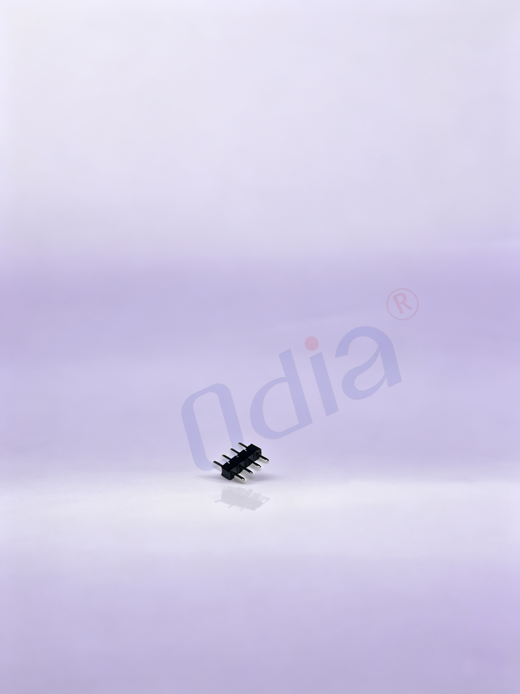
What Are Pin Headers?
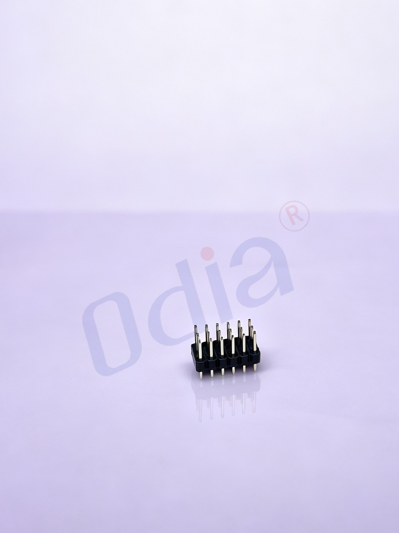
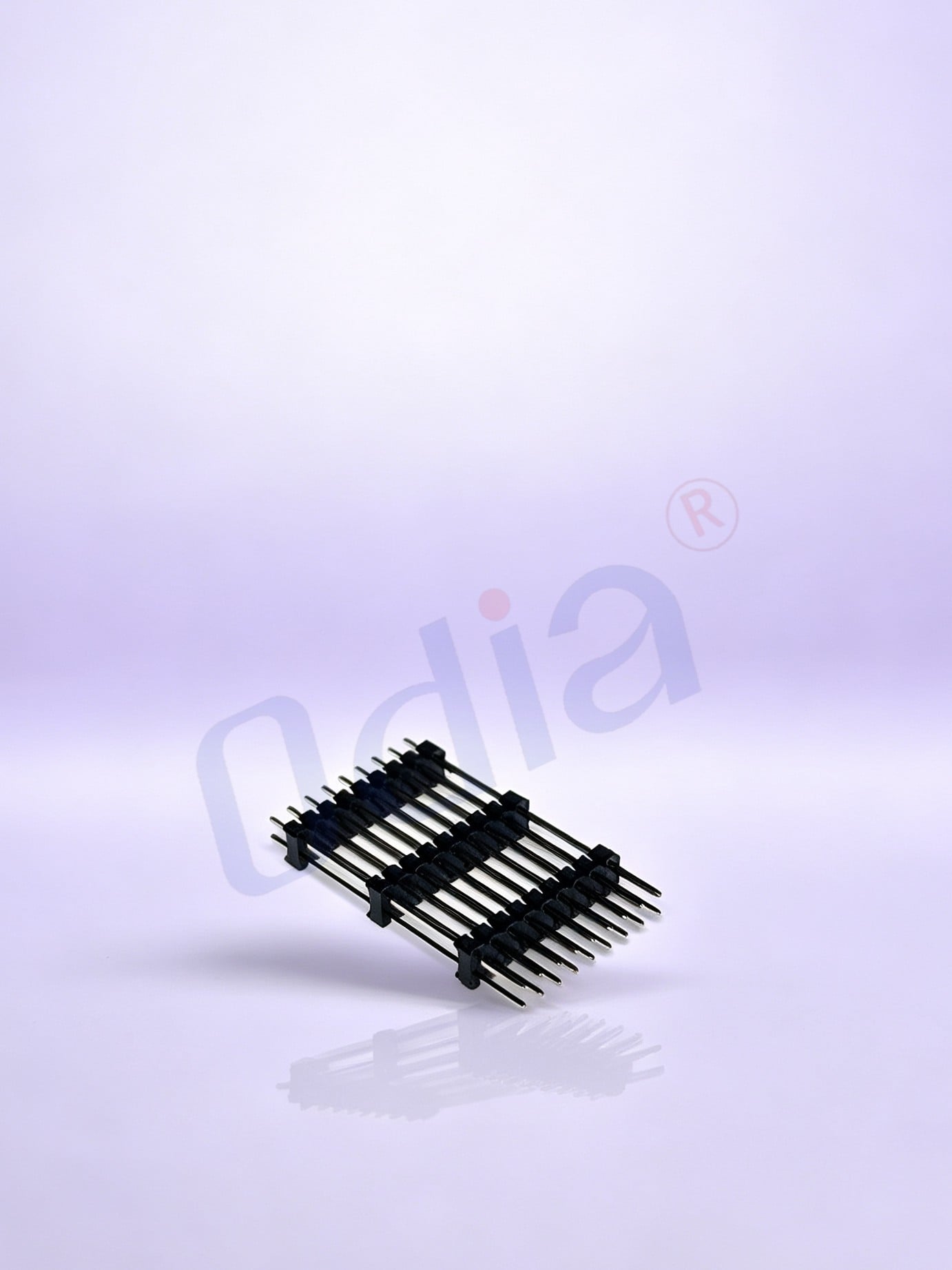
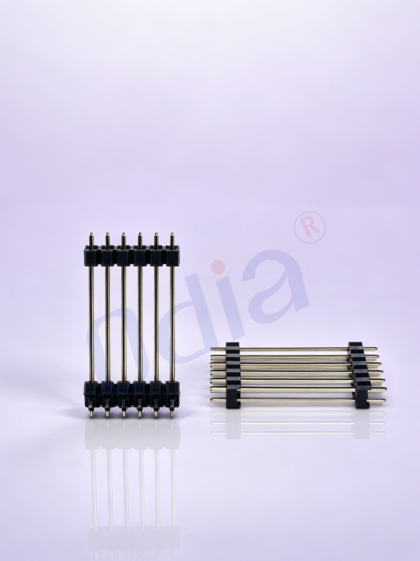
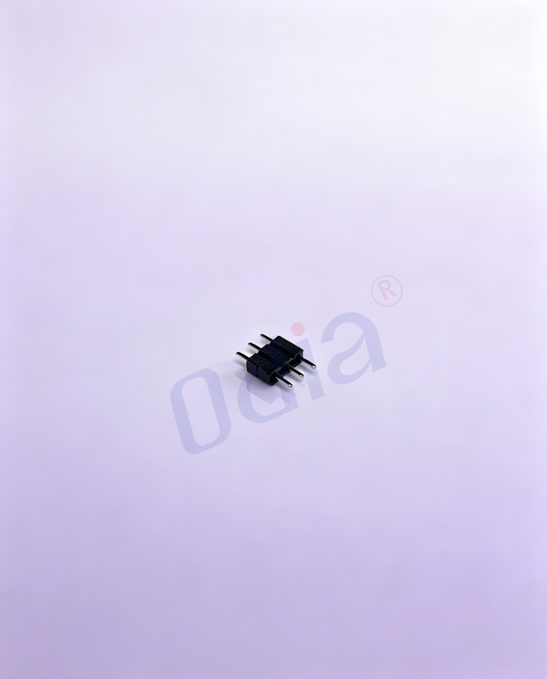
Pin headers are the male side of a PCB board-to-board connector system. They consist of one or more rows of metal pins—available in both square-hole and round turned-pin configurations—encapsulated in a molded plastic insulator, and are mounted directly onto a PCB through through-hole (DIP) or surface-mount (SMT) processes. In their most common form, pin headers provide a reliable, low-cost connection interface for signal and power routing across a wide range of electronic assembly designs.
This category covers a broad selection of pitch sizes (1.27mm, 2.0mm, and 2.54mm), mounting orientations (straight DIP, 90-degree right-angle, and SMT), row configurations (single and double row), and insulator constructions—including standard single-insulator, dual-layer, triple-layer, gate-type, U-type, and SMT-optimized variants. This range means a single product category can serve everything from legacy industrial control boards to compact IoT sensor modules and next-generation embedded system designs.
Key Product Characteristics
- Pitch options: 2.54mm (industry standard), 2.0mm, and 1.27mm—covering both mainstream legacy designs and fine-pitch compact PCBs
- Mounting styles: Straight 180-degree through-hole DIP, 90-degree right-angle through-hole, and surface mount (SMT) for reflow assembly
- Pin types: Square hole and round turned pin, each offering different contact geometry and retention characteristics
- Row configurations: Single row (1×n) and double row (2×n), selectable by pin count and interface density requirement
- Insulator variants: Standard, dual-layer (enhanced vibration resistance), triple-layer, gate-type (keyed middle-pin layout for error-proofing), and U-type (U-shaped bend for improved assembly stability in constrained spaces)
- Housing material: PA6T insulator for thermal stability and dimensional consistency; brass contact pins with plated finish for reliable conductivity
- Compliance: Products in this range are designed for RoHS and UL compatibility. If specific certification documentation is required for your application or supplier qualification process, confirm the current applicable compliance scope before BOM finalization.
Common Applications
Pin headers appear across virtually every segment of modern electronic manufacturing, from high-volume consumer assembly to precision industrial systems:
- Industrial automation: PLC interface boards, sensor module interconnects, actuator driver circuits, and robot controller cards frequently rely on 2.54mm and 2.0mm pin headers for modular and maintainable PCB-to-PCB connections
- Automotive electronics: Compact fine-pitch headers (1.27mm, 2.0mm) serve ECU daughter boards, battery management system modules, and sensor interface sub-assemblies where board real estate is a primary constraint
- IoT and embedded systems: The 2.54mm pin header remains standard for prototyping platforms, microcontroller breakout boards, and development hardware; fine-pitch variants are increasingly common on higher-density production boards
- Medical devices: Through-hole pin headers with RoHS-compliant materials are preferred for internal board interconnects in medical equipment where long-term contact stability and traceability documentation are design requirements
- Data communications and consumer electronics: Both DIP and SMT pin header variants support signal routing on gateway hardware, communication interface modules, and consumer device main boards
How to Choose the Right Pin Header
Pitch selection
You already know that 2.54mm is the de facto standard for most through-hole designs—and for good reason. It is compatible with the widest range of mating female headers, development boards, and off-the-shelf cabling. But the real constraint in compact PCB layouts is often mating height clearance, adjacent component spacing, and whether your production line is tooled for fine-pitch handling. If board area is tight and your assembly process can support it, 2.0mm or 1.27mm pitch pin headers allow meaningfully higher density within the same footprint boundary.
So which pitch should you actually start with? If your design involves compact form factors—IoT modules, wearable electronics, or high-density control boards—2.0mm or 1.27mm may be the right starting point. If you are designing a general-purpose control board, prototyping platform, or any assembly where cross-supplier compatibility is a priority, 2.54mm remains the practical and lower-risk choice. Neither option is universally better: 2.54mm excels when ease of assembly and broad mating compatibility matter, while fine-pitch variants are more appropriate when board density requirements drive the design.
Mounting orientation: straight vs. right-angle
Choosing between a straight (vertical) and a right-angle pin header is not just about board height clearance. The more common decision driver is cable or connector routing direction—specifically, whether the mating female connector must exit horizontally relative to the board, and whether the enclosure or chassis constrains vertical mating access. Right-angle pin headers are frequently preferred when the harness must face a panel cutout, or when vertically stacked boards limit the clearance needed for a straight mating connector.
If the assembly process involves automated PCB insertion, straight DIP pin headers are generally easier to fixture and inspect. If the final assembly involves manual cable connection within a confined enclosure, right-angle mounting often results in a more accessible and serviceable connection point.
Through-hole vs. SMT
Through-hole pin headers offer stronger mechanical retention and are better suited for connectors that will see repeated mating cycles or vibration exposure in field use. SMT pin headers—including the square-hole SMT variants in this catalog—are optimized for high-volume automated reflow production lines where placement accuracy and process consistency are the primary goals. If your production line runs automated SMT assembly and the design does not require high mating-cycle durability, SMT headers reduce per-unit assembly labor and improve board space utilization.
Insulator configuration: standard, gate-type, and U-type
Standard single-insulator pin headers work for the majority of signal routing applications. Gate-type pin headers—which have one or more pin positions intentionally left empty as a keying feature—are used where misconnection risk is a concern; the keyed position makes reversed or offset mating physically impossible, which is valuable in multi-connector assemblies where adjacent connectors share the same pitch and housing dimensions. U-type pin headers, with their U-shaped bend and square-hole positioning structure, improve plug-in stability and reduce insulator loosening in tight assembly spaces where a standard header would have insufficient lateral retention.
Dual-layer and triple-layer insulator variants add mechanical reinforcement and improve vibration resistance—relevant in automotive electronics and industrial control applications where connectors may be exposed to continuous mechanical vibration loads.
A note on footprint and dimensional compatibility
A common mistake when sourcing pin headers from a new supplier is assuming that the PCB footprint is interchangeable. Pin length, through-hole land diameter, and pin-to-insulator height can vary between manufacturers in ways that affect solder joint geometry and adjacent component clearances. If you are qualifying an alternate source for an existing design, verify the dimensional drawing against your current PCB footprint before placing a first-article order—identifying a footprint mismatch before first-article inspection is far less costly than a mid-production board revision.
Procurement and Sourcing Considerations
Pin headers are among the more standardized product types in PCB connectors, but standardized does not mean unconditionally interchangeable. For procurement teams managing production BOMs, the key sourcing criteria are: pitch and mounting type match, dimensional drawing alignment with existing PCB footprint, insulator material temperature rating relative to process and operating conditions, and compliance documentation coverage for your target market regions.
For buyers supplying into European markets, RoHS compliance documentation is a baseline entry requirement. For Japanese and Korean buyers, formal quality documentation including material declarations and supplier traceability records are typically part of the qualification process. If you are evaluating an international pin header supplier for the first time, requesting dimensional drawings, compliance certificates, and a physical sample for first-article inspection is standard practice before BOM commitment.
If your design is in the shortlisting phase and you are weighing pitch, configuration, and mounting options against your PCB layout and production process, application-specific technical guidance is available to help narrow the specification without extended back-and-forth on dimensional interpretation.