
 EN




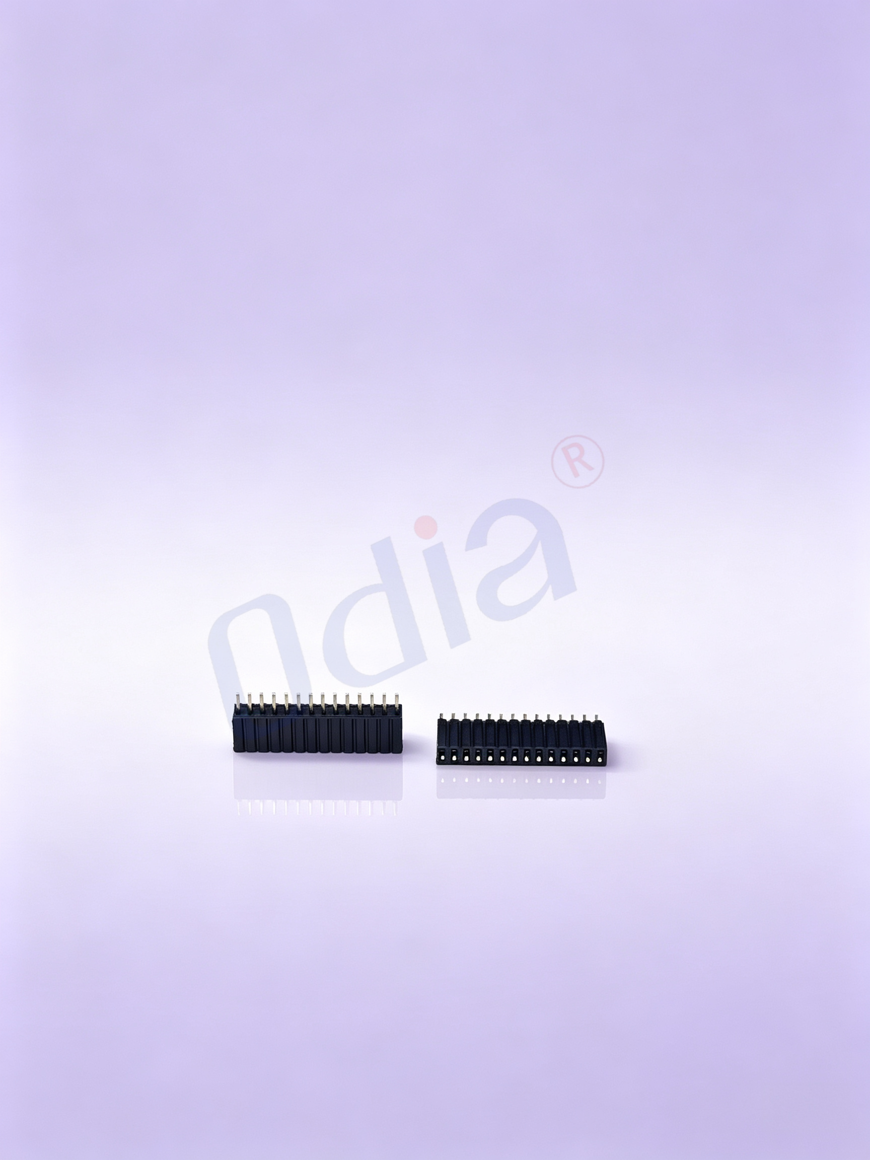
What Are Female Header Connectors?
Female header connectors—also called female headers or socket headers—are the receptacle counterpart to pin headers, designed to accept male pins and create a removable, reliable electrical interface on a PCB. Each contact uses a precision spring geometry to grip the mating pin securely, maintaining consistent contact force across rated mating cycles. This spring-loaded engagement is what distinguishes a well-specified female header from a generic socket: the contact normal force determines both electrical resistance stability and long-term retention performance.
In PCB design, female headers are specified alongside their mating pin headers as a matched pair. The common pitch sizes—2.54mm (0.1 inch), 2.0mm, and 1.27mm—define the center-to-center spacing of the contacts and must match exactly between male and female halves. This category covers the full range of PCB-mount female header formats: straight DIP (through-hole), right-angle DIP, and surface-mount (SMT) variants, in both single-row and double-row configurations. Two contact socket types are available—square hole and round claw-spring—each suited to different pin geometry and contact retention requirements.
Key Product Characteristics
- Contact Spring Design: Female headers with precise contact spring geometry maintain consistent insertion force and contact normal force across rated mating cycles. The contact spring material—typically phosphor bronze or beryllium copper alloy—determines how well the contact retains its clamping force over the product service life, particularly in applications with repeated mating cycles or elevated ambient temperatures. Phosphor bronze provides a reliable cost-performance balance for general-purpose applications; beryllium copper is specified where higher spring-back force and fatigue resistance are required.
- Pitch Options: Standard pitches of 2.54mm, 2.0mm, and 1.27mm cover the majority of PCB layout requirements. The 2.54mm pitch remains the most widely used for general-purpose signal interfaces and breadboard-compatible development boards. The 2.0mm and 1.27mm pitches are increasingly specified in compact designs where board area is constrained. Going to a finer pitch like 1.27mm improves board density, but it also increases the risk of manual assembly error and tighter tolerance requirements on the mating PCB footprint—a tradeoff worth making explicit before finalizing the layout.
- Mounting Types: Through-hole DIP female headers provide robust mechanical retention for manual assembly and applications subject to mechanical stress. Right-angle DIP variants allow horizontal connector exit, optimizing routing where board clearance is limited. SMT female headers are compatible with reflow soldering profiles and automated PCB assembly lines, with high-temperature nylon or LCP housing materials rated for 260°C peak reflow temperatures.
- Row Configuration: Single-row female headers are used for standard signal breakout connections. Double-row configurations increase pin density within the same footprint and are common in applications requiring more circuits without expanding the PCB area allocated to the connector.
- Contact Plating: Both standard tin and gold-plated contact finishes are available. Gold plating is often assumed to be the premium default for female headers in all applications—well, actually, for applications where mating cycles are low and the environment is controlled and dry, tin plating delivers comparable long-term reliability at meaningfully lower cost. Where corrosion resistance matters, such as high-humidity environments or critical signal integrity requirements, gold plating provides a measurable advantage in contact resistance stability over product lifetime.
- RoHS Compliance: Female headers across the full pitch and configuration range are available with RoHS-compliant materials, meeting hazardous substance restrictions for products sold into the EU, Japan, and other regulated markets. Custom pin counts and housing color options are available to support product differentiation or assembly error-proofing requirements.
Common Applications
You already know that female header connectors appear across virtually every category of electronic equipment. What is worth focusing on is how the specific application environment drives specification choices—and where generic selection assumptions tend to create problems.
In industrial automation, female headers are used in PLC I/O boards, sensor interface modules, and control board interconnections. Reliability requirements are high because connection failures in automated production lines translate directly into downtime costs. Contact spring retention and housing dimensional stability under thermal cycling are the relevant performance parameters—not just initial contact resistance.
In robotics and motion control, repeated mating and unmating cycles during maintenance place real demands on contact spring fatigue resistance. Female headers in these applications benefit from phosphor bronze or beryllium copper contact springs that maintain clamping force across the service life of the connection, not just at initial assembly.
In medical devices and instrumentation, documentation requirements extend beyond electrical and mechanical performance. Material traceability, RoHS declarations, and quality process documentation are threshold requirements for procurement approval. The guidance in this section aligns with the general direction of connector performance standards applicable to medical and industrial electronics; if a specific standard number is to be cited for a given application, confirm the current active version and applicable edition before use.
In data centers and server hardware, fine-pitch female headers at 1.27mm and 2.0mm pitch are used in board-to-board and wire-to-board interfaces within server chassis. Contact resistance stability over the equipment operating life is the primary specification concern, making gold-plated contacts the standard choice in this segment.
In consumer electronics development and prototyping, 2.54mm pitch female headers provide the removable interface that allows boards to be separated for programming, testing, and rework without soldering. This remains the standard pitch for development boards and evaluation kits because of its breadboard-compatible spacing.
How to Choose the Right Female Header
So which female header specification should you start with? That depends on whether your priority is board density, solder process compatibility, ease of manual assembly, or mating cycle life—and those factors do not always point to the same specification.
Start with pitch compatibility. The female header pitch must match the mating pin header exactly. A common issue when sourcing across multiple vendors is discovering that products marketed as compatible with standard 2.54mm footprints have pin pitch tolerances wide enough to cause intermittent contact when mated with boards from other suppliers—particularly in board-to-board stacking configurations. Verifying dimensional drawings, not just the nominal pitch specification, is the practical step that prevents this category of field problem.
Verify the PCB footprint before committing to a supplier. A common mistake when specifying female headers is assuming the footprint is interchangeable across vendors—only to discover that housing body width and pin entry tolerances vary enough to cause fit or solder joint issues during first-article inspection. Matching the female header to the specific PCB layout file, including hole size for DIP variants or pad dimensions for SMT variants, avoids late-stage board revision costs.
Select mounting type based on the assembly process. Through-hole DIP is preferred when mechanical retention and manual assembly solderability are priorities. SMT is preferred for automated reflow lines where pick-and-place consistency and coplanarity are required. Right-angle variants serve applications where the mating connector must exit horizontally relative to the PCB surface.
Match contact plating to the operating environment. For high-humidity environments, critical signal integrity applications, or high mating cycle life requirements, gold-plated contacts are justified. For controlled-environment, low-cycle applications, tin plating provides adequate reliability at lower cost.
Confirm housing material against the assembly temperature profile. For SMT applications using standard reflow profiles, LCP or high-temperature nylon housings rated to 260°C are required. For through-hole wave soldering, standard nylon housings are adequate under typical process temperatures.
Procurement Considerations for B2B Buyers
The connector market is highly fragmented, with many manufacturers offering overlapping product ranges at similar price points. For buyers without deep category expertise, differentiating suppliers on catalog specifications alone is difficult—and the differences that matter, such as contact spring geometry consistency, housing dimensional tolerances, and plating process control, are not always visible in a standard datasheet comparison.
- Multi-pitch coverage: For designs that span legacy 2.54mm interfaces and next-generation 1.27mm or 2.0mm fine-pitch connections, working with a supplier who maintains product depth across all three pitch sizes reduces sourcing complexity within a single BOM. The trend toward miniaturization in compact industrial controllers, IoT modules, and wearable devices is sustaining demand for fine-pitch variants—confirming long-term supply availability before BOM finalization is a practical procurement step.
- Plating options: Access to both tin and gold-plated variants from the same product line simplifies specification decisions: the plating is selected based on application requirements, not constrained by what the supplier stocks.
- Sample and prototype support: Engineering teams that need female header samples for design validation benefit from suppliers who support small-batch prototype orders without requiring production-level minimum quantities. Verifying fit, mating force, and PCB footprint compatibility before production commitment is the standard approach that avoids late-stage design changes.
- Compliance documentation: EU-targeted products require current RoHS declarations and, depending on the application, REACH substance declarations. Verifying that the connector supplier maintains current compliance documentation reduces procurement friction during final product certification and import clearance.