
 EN



The Small Part That Makes or Breaks Your Prototype
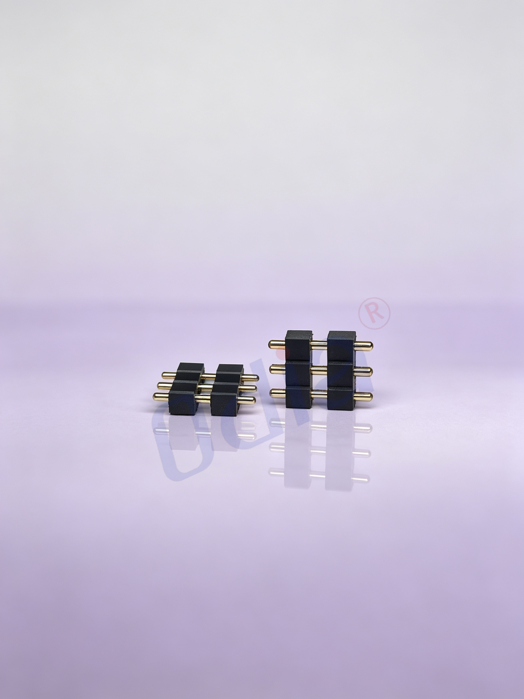
Header pins are the least glamorous components on a PCB. They cost pennies, occupy minimal board space, and rarely make it onto a bill of materials highlight reel. Yet choosing the wrong header can derail a prototype faster than almost any other passive component. A header with insufficient current rating overheats. A header with the wrong pitch will not mate with the intended receptacle. A header with unsuitable plating develops intermittent contacts after a few mating cycles.
The selection process is not complicated, but it requires attention to five parameters that interact with each other: pitch, current rating, material, mounting type, and plating. Getting those five right eliminates the vast majority of header-related problems in prototyping and early production.
Pitch Selection: The Parameter That Constrains Everything Else
Pitch is the center-to-center distance between adjacent contacts, and it is the first decision because it determines mating compatibility, PCB routing density, and mechanical clearance. The 2.54 mm pitch is the de facto global standard for general-purpose headers, the one that mates with breadboards, Arduino shields, Raspberry Pi HATs, and the vast majority of development platforms.
For prototyping, 2.54 mm pitch is almost always the right starting point. The larger geometry is forgiving of solder bridges, the pins are easy to probe with test equipment, and the wide availability of mating connectors means design changes do not require a complete re-layout.
Fine-pitch options become necessary when board space is constrained. The 2.00 mm pitch offers a moderate reduction in footprint, while 1.27 mm and 1.00 mm pitches support very dense designs. These smaller pitches increase routing density but demand tighter tolerances for footprint accuracy, solder paste deposition, and component placement. For a prototyping board where a few extra square millimeters are available, the mechanical robustness of 2.54 mm pitch usually outweighs the space savings of finer pitches.
One pitfall worth noting: mixing pitch families on the same board. If one header is 2.54 mm and another is 2.00 mm, the risk of accidentally mating the wrong cable or jumper set increases significantly. Standardizing on a single pitch for all headers on a prototype board, whenever space permits, simplifies assembly and reduces error potential.
Current Rating and the Thermal Reality of Small Contacts
Header current ratings vary widely depending on contact size, material, and ambient temperature. A 2.54 mm header with brass contacts and gold plating might be rated for 3A per pin at room temperature, while a larger-pitch header with more substantial contacts can handle 7.5A or more.
The critical detail is that current ratings are specified at a given temperature rise, typically 30°C above ambient. In an enclosed prototype enclosure with poor airflow, the ambient temperature inside the box can be significantly higher than room temperature. A header rated for 3A at 25°C ambient may only be good for 1.5A or 2A at 50°C ambient.
For power distribution headers, the safe approach is to derate the published current rating by at least 50% and to distribute current across multiple pins where possible. Using two or three pins in parallel for power and ground connections reduces the current per contact, lowers the temperature rise, and provides redundancy if one contact develops higher resistance over time.
| Parameter | Typical Options | Prototyping Recommendation |
|---|---|---|
| Pitch | 2.54 mm, 2.00 mm, 1.27 mm | 2.54 mm for general use |
| Current Rating | 1A to 7.5A+ per pin | Derate 50% for enclosed designs |
| Insulator Material | PBT, PA9T, LCP | LCP for reflow soldering |
| Plating | Tin, Gold Flash, Gold over Nickel | Gold over Nickel for reliability |
| Mounting | Through-hole, SMT | Through-hole for prototypes |
Reference values consolidated from PCB header selection guides.
Material Choices That Affect Solderability and Longevity
The insulator material determines how the header behaves during soldering and how it performs over time. The three common options are PBT, PA9T, and LCP.
PBT is the most economical option and handles hand soldering without issue. Its temperature resistance is marginal for reflow soldering, however, and it can deform if exposed to higher-than-rated temperatures.
PA9T offers better thermal performance than PBT and is suitable for many reflow processes. It balances cost and performance for general-purpose applications.
LCP, or liquid crystal polymer, is the premium choice. It maintains dimensional stability at high temperatures, making it suitable for lead-free reflow soldering profiles that peak above 260°C. LCP also has excellent electrical properties and low moisture absorption. For prototypes that will transition directly into production without a header change, LCP is often worth the small cost premium.
The plating choice affects both solderability and contact reliability. Tin plating is inexpensive and solders well, but tin oxide buildup can increase contact resistance over time, particularly in humid environments. Gold flash, typically 3 to 5 microinches over nickel, provides a good balance of cost and reliability for connectors that will see a moderate number of mating cycles. Thicker gold, 15 to 30 microinches, is appropriate for headers that will be mated and unmated frequently or that must maintain low contact resistance in harsh environments.
Through-Hole vs. Surface Mount: A Decision Based on Prototype Priorities
Through-hole headers dominate prototyping for good reason. The mechanical connection is robust, the solder joints are visible and easy to inspect, and the headers can be installed by hand without a reflow oven. The pins protrude through the board, which makes them easy to probe with oscilloscope leads or logic analyzers.
Surface-mount headers save board space on the top side and enable cleaner reflow assembly. Their mechanical strength depends entirely on the solder joint, however, and they are more susceptible to damage from lateral forces during probing or cable insertion. For prototypes that will be handled frequently or that use heavy cable assemblies, through-hole mounting is the safer choice.
Mixed-technology designs sometimes use through-hole headers for power and signal I/O, where mechanical robustness matters, and surface-mount headers for board-to-board interconnects, where space is at a premium and the boards are mechanically supported by standoffs.
A Quick Checklist for Header Selection in Prototyping
Five questions cover the essential selection criteria. First, what is the mating connector's pitch, and does the header match it? Second, what is the maximum current per pin, and has the rating been derated for the actual ambient temperature inside the enclosure? Third, does the insulator material survive the soldering process without deformation? Fourth, is the plating appropriate for the expected number of mating cycles and the operating environment? Fifth, does the mounting type match the mechanical requirements of the application?
Running through those questions before placing a header on the BOM prevents the most common prototype failures. None of the answers are complicated, but overlooking any one of them can turn a straightforward prototype build into a debugging session that consumes days.
For engineering teams that need headers and cable assemblies as a matched system, sourcing both from a manufacturer that produces connectors and assemblies under one quality framework simplifies the validation process. Odia Electronics manufactures pin headers and cable assemblies through dedicated production operations, which means the mating interfaces and contact specifications are controlled from a single source.
Table of Contents
- The Small Part That Makes or Breaks Your Prototype
- Pitch Selection: The Parameter That Constrains Everything Else
- Current Rating and the Thermal Reality of Small Contacts
- Material Choices That Affect Solderability and Longevity
- Through-Hole vs. Surface Mount: A Decision Based on Prototype Priorities
- A Quick Checklist for Header Selection in Prototyping

